![]()
![]()
( by )
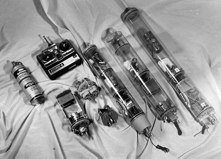
I've developed a removable water tight container to ease installation of equipment and to facilitate adjustment and repair, so I can keep my r/c submarine working at the pond without having to go home to fix a minor problem that required a work-shop to access. About 18 months ago I settled on using a length of clear Lexan tube to form the structure of a removable control, propulsion, and variable ballast system.
Since developing the smaller (3" outside diameter) water tight cylinder (WTC) for my
SKIPJACK kit, I discovered the need for a similar setup for larger r/c submarines. They
needed a ballast tank of greater capacity and a more powerful propulsion motor. So I
developed a 3.5" diameter WTC.
Using a cylinder of only a half inch larger diameter than the smaller unit to house the r/c and ballast system would, at first thought, not seem to afford much advantage. But, what a difference in internal volume a half inch makes! The new cylinder, dubbed the WTC-3.5, can easily accommodate standard size servos, side by side; the tall APC-1; any speed controller; and the large Pittman or Graupner motors, and with room to spare.
The increased volume in the ballast tank section of the cylinder makes for a shorter tank
- a tank, incidentally, which has a movable forward bulkhead (piston) which is adjusted by
a jacking screw. Moving the piston in or out of the tank sets it up for a specific volume
of ballast water, making the system readily adjustable for different boat installations.
As with the WTC-3, this larger unit is made by cutting a length of Lexan tube to size,
drilling out various holes to accommodate bulkhead mounting screws, form ballast tank
flood/drain ports, vent valve opening, and penetrations for the tire-valve.
The thing that makes the clear lexan cylinder work as a water tight containment and
ballast tank are the disc shaped bulkheads I cast from polyurethane resin. Unlike the
smaller WTC-3, the WTC-3.5 does not house the propulsion/control battery in a watertight
space; the big gel-cell battery is mounted wet in the hull, the two leads from the battery
making up to lug connectors on the face of the after motor bulkhead.
The after dry section of the cylinder houses the r/c equipment, angle keeper, speed
controller, servos, fail-safe circuits, and motor. The motor bulkhead seals the after end
of the cylinder via a water tight O-ring which fits a grove within the bulkhead. Four
Sub-Tech water tight seals exit the top of the motor bulkhead and permit three servo
outputs and one for the on/off switch. The motor output goes through a Sub-Tech 3/16"
stuffing tube bearing and water tight seal fit within a shaft extension cup itself
secured, via four machine screws to the after face of the motor bulkhead, the union
between the two units made water tight by an O-ring seal.
The motor output at the wet end of the seal terminates in a spur gear which meshes with
the drive gear of the excellent 3:1 reduction box offered by Engineered Specialties. Since
the gear box is operated in a wet environment several drainage holes have to be drilled
into the housing to permit complete drainage after use.
Cast resin mounting hardware, used to secure the equipment within the water tight
portion of the WTC, includes two extended mounting brackets which attach to the inside
face of the motor bulkhead and to which are hung the servo tray and equipment mounting
bulkhead (to which are secured two horizontal equipment trays). Machine screws are used
throughout to secure one piece of mounting hardware to the other making for quick
adjustment, relocation, or replacement of control and propulsion devices.
Other cast resin parts that make up the WTC-3.5 include the ballast tank volume adjustment
piston, piston jacking screw bearing, special servo output arms and bow plane swing-arm
linkage.
This cast resin piece separates the dry and wet sides of the cylinder. Built into the
ballast bulkhead is a cavity which houses the ballast system servo, vent/blow actuation
support brackets and foundation which secures the Clippard SMAV-3 blow valve.
The wet side of the ballast bulkhead has five foundation tabs, each drilled and tapped to
accept 6-32 brass machine screws which secure the bulkhead firmly within the cylinder.
A unique feature of the ballast system is a 'gas saver linkage disconnect'. Fancy words to describe a device, worked by a float, that disengages the actuation arm when the ballast tank is dry, stopping the discharge of Propel gas during the blow, greatly increasing the number of blows between charging. This device alone has increased the number of blows available from a single charge by about 30%!
The ballast system servo operates a 1/8" rod which extends into the wet side of the
ballast tank bulkhead. The end of the push-pull rod is threaded to take 6-32 nuts which
sandwich the bottom end of the actuation arm. The two nuts are adjusted to set the
distances the actuation arm travels to actuate the vent and blow valves.
After installing the WTC-3.5 within the model submarine hull, a 'trial and error' set-up of the ballast tank volume is done in a test tank to determine the specific amount of volume needed within the ballast tank to float the model at its correct waterline. This is done by sitting the model in the water with all control devices, batteries, and running gear installed, and a full charge of Propel in the bottle and running the ballast tank piston in or out until the right amount of reserve buoyancy is achieved. A piece of narrow electrician's tape is then placed over the Lexan tube right over the ballast piston o-ring to mark the correct volume setting for that specific model hull.
Later, when setting up the floodable volume for other submarine hulls you will have a
series of reference marks on the cylinder to quickly guide you as you set up the WTC for
each specific application. One size fits all.
With the servo in 'neutral' the upper ballast tank vent (a rubber plunger fitting within a
hole drilled at the top of the Lexan tube) is shut, and the actuation arm and the gas
saver linkage attached to it is clear of the blow valve stem. Nothing happens.
To vent the tank, the servo drives the push-rod aft, to the 'vent' position, and the
after adjustment nut pushes the actuation arm aft, it rotates around the upper pivot pin,
bringing the vent valve rubber plunger off its seat and air is vented out of the tank as
water comes in through the open holes in the bottom of the tube to displace the escaping
gas. The model sinks to a near neutral buoyancy.
When commanded to 'blow', the push-rod is pulled forward and the after adjusting nut
carries the actuation arm (and the gas saver linkage) into contact with the blow valve
stem, releasing Propel gas into the ballast tank, the over pressure forcing water out the
holes in the bottom of the ballast tank (the vent valve remains closed, the actuation arm
only flexes a bit). The model floats to the surface.
When the ballast tank is full of water the gas saver unit (attached to the lower portion
of the linkage arm) is cocked and ready to make contact with the blow valve stem when ever
the actuation arm is moved to the blow position. The attached float, buoyed by the water,
keeps the blow part of the system armed until the tank is dry, at which point the float
drops, disconnecting the gas saver linkage from making contact with the valve stem,
automatically securing the blow.
Propel type liquid/gas is kept in a copper bottle mounted within the ballast tank, At the top of the bottle is soldered a standard tire-valve used to charge the bottle from a Propel can. A barbed hose connection on the side of the bottle taps the gas and, through a 1/16" hose, leads it to the input side of a Clippard SMAV-3 blow valve.
Now, for those boats big enough, you can disconnect the installed bottle from the valve
and use a full can of Propel, mounted elsewhere in the hull as your gas source. The hose
from the external supply entering the ballast tank through one of the two open holes in
the bottom of the tank and on into the input side of the Clippard valve.
Or, you can build up a CO2 gas system (described in previous issues of the Report) and route the regulated low pressure gas to the SMAV-3 as above. Plenty of options!
And that should demonstrate for you the beauty of the WTC concept: a complete control, variable ballast, and propulsion system in one package that can be quickly moved from one hull to the next. Think of the cost savings now that you don't have to purchase a set of devices for each model submarine in your 'fleet'!